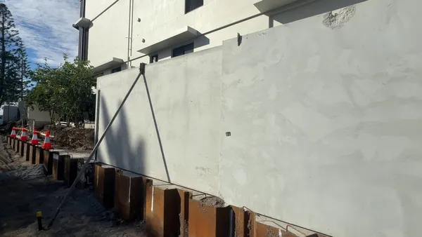
Pour day. In the last post I showed you the boundary fence footing we designed with our engineer instead of using the fence company's standard detail. This one is the pour itself, from the last check of the steel through to a finished, floated footing.
There are four videos this time. I only talk in the first one. We forgot to record sound on the rest, so I've written up what's happening in each, and added a few sketches to explain what the steel and the concrete are actually doing.
The plan for the pour
We ordered 10 cubic metres of 40 MPa concrete with 20 mm aggregate and an 80 mm slump. That meets the engineer's specification: N32 minimum strength, 20 mm maximum aggregate and 80 mm maximum slump. Strength and slump are both explained further down.
No pump on this one. We pushed the fill that was sitting on this side of the site out of the way so the trucks could reverse right up to the edge and place the concrete straight off the chute. That saves the cost of a pump, which is always nice.
The order of work:
- Start at the far end. The open end is where we'll connect the rest of the wall later, so we pour away from it.
- Vibrate as we go. The poker vibrator settles the concrete around the steel and gets the air out.
- Bring it down to level, then finish with a mag float.
Last walk-through before the trucks
This is the walk along the trench just before the concrete arrived. A few things to point out.
The engineer has signed off. Our structural engineers, Westera Partners, inspected all of the reinforcement and found nothing to fix. Their report had two reminders for pour day: keep the cores clear of debris and water, and hold the cover while the concrete goes in. I passed a copy straight on to the fence company, because the starter bars and the fence itself are their design and their certification.
The fence verticals aren't in. The tilt panel fence contractor was meant to come out the day before and fix their vertical bars into the cage. We'd given them two weeks. They didn't turn up, so they're coming this morning to set their bars into the wet concrete. Not what we wanted, but it's what we've got.
To make that as easy as possible, we marked the centre line of the fence and the outside face of the precast panels on a sheet of ply at the end of the trench. We've also marked the boundary line on the wall. Once the concrete goes off, their bars get bent up into position.
The round tubes are void formers. Those are Formatubes, packed with sand. Later we drill them out and drop in spear points for the dewatering, which I covered in the last post.
Jack points for the neighbour's path. We hand dug a couple of small offsets under the edge of the neighbour's path. The footing runs at least 300 mm under there, so we can jack off it later. The pre-drilling for the sheet piles dropped that path by about 20 mm along one direction. It's still level the other way. The plan is to push it back up. If that doesn't fix it, the fallback is a topping slab and new tiles on that side. We get on really well with our neighbours, so we'll take it one step at a time and talk it through with them.
Stop end and tie bars. There's a small stop end boxed in at the end, and a bundle of slab tie bars ready to go in at the marks. More on those below.
Why we didn't use the standard footing
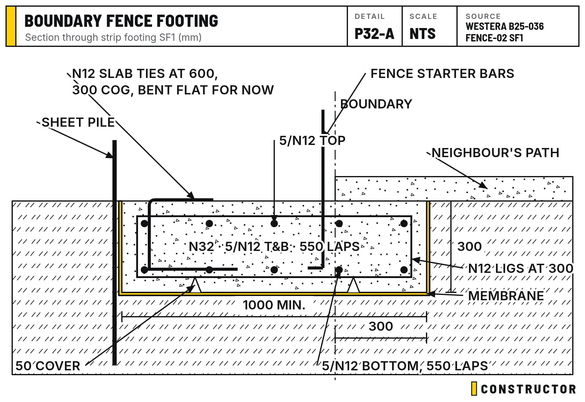
The fence company's detail was a 1 m deep bored pier. For a site where the pre-drilling has disturbed the ground, we didn't think that was good enough. So our engineer designed a reinforced strip footing for this site instead. On the drawing it's at least 1,000 mm wide and 300 mm deep, and it runs at least 300 mm past the boundary under the neighbour's side. That extra width is what we'll jack the neighbour's path off.
This isn't about questioning everything a supplier tells you. It's about making sure what you're quoted actually suits your site. A lot of people are selling apples. Even if you need an orange, some will still sell you an apple, because apples are all they know how to sell.
What the steel is doing
Here's what you're looking at in the cage.
- Main bars. Five N12 bars along the top and five along the bottom (written "5/N12 top and bottom" on the drawing) carry the load along the length of the footing. N12 means a 12 mm deformed bar.
- Ligatures. These are closed N12 ties at 300 mm centres. They hold the main bars in position, so nothing moves when the concrete hits it.
- Slab ties. N12 bars at 600 mm centres, with a 300 mm cog (the bent leg) inside the footing. They'll tie the future ground slab into this footing.
- Bar chairs. These plastic stands hold the cage up off the membrane. The engineer's notes call for them at no more than 800 mm centres.
- Cover. This is the concrete between the steel and the ground. It's what protects the steel from moisture and rust. Our drawing calls for 50 mm to the ground. As a general rule, AS 3600 adds extra cover where concrete is cast against the ground: 10 mm more with a membrane underneath, 20 mm more without one. Check the cover with a tape before the pour, not after.
Laps and splices
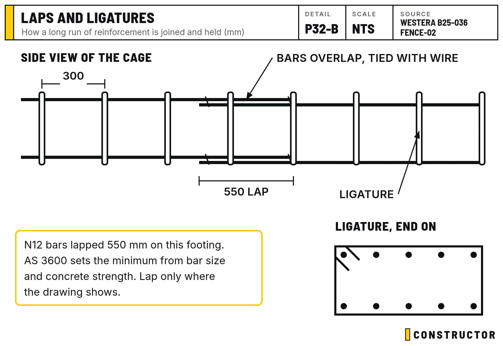
Reinforcing bars come in fixed lengths, so on a long run they have to be joined. The usual way is a lap, also called a lapped splice. Two bars overlap side by side and get tied together with wire.
The lap length matters. If it's too short, the load can't transfer from one bar to the next. Your engineer specifies it, and AS 3600 works it out from the bar size and the concrete strength. On this footing the N12 bars are lapped 550 mm. The engineer's notes also say to lap only where the drawing shows, or where they've approved it.
The truck arrives
No sound on this one. The first Hymix agitator reverses down the access we cleared, between the sheet piling and the site. I'm guiding the driver back to the far end of the trench. You can see the laser level set up on its tripod and the gear laid out: shovels, the vibrator, and the level staffs. The driver swings the chute out over the sheet piling so it reaches the footing.
Placing it straight off the chute
Again, no sound. The concrete goes from the chute straight into the trench and works its way through the cage. Here's what to watch for:
- The string line running along the neighbour's side, so we keep to the boundary.
- The yellow capped pegs, which are our level marks for the top of the footing.
- The poker vibrator going in as the concrete builds up, so it settles around the bars and into the corners.
- The chute being moved along a section at a time, so we never drop concrete from a great height or push it a long way sideways.
Slump and strength: the two numbers on the docket
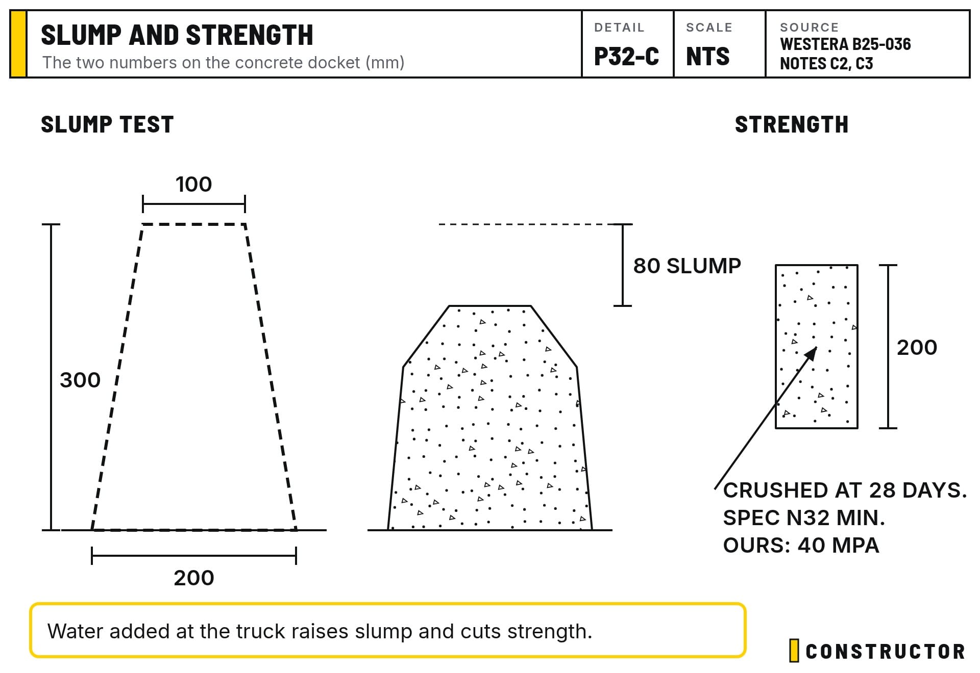
Slump tells you how wet and workable the mix is. A cone is filled with concrete and lifted off, and the slump is how far the concrete drops. At 80 mm, the mix is firm but still workable. With the poker vibrator, it places from a chute and settles through the cage without being sloppy. The engineer capped the slump at 80 mm. A wetter mix is easier to place, but it shrinks and cracks more.
Strength is measured in MPa. Test cylinders are crushed at 28 days. Our drawing calls for at least N32, which means 32 MPa. The mix we used is rated at 40 MPa.
One warning. Adding water at the truck raises the slump, but it lowers the strength. If someone wants to add water on site, they should ask you first, and it should be noted on the docket.
The finished footing
No sound again. This is the walk-around after the finish. The top has been screeded to the level marks and mag floated. Things to look for:
- The sheet piling that formed one side of the pour, still with our "outside face precast" marking on it.
- The slab tie bars bent flat at the surface. When the sheet piling is cut down and we do the external concreting, they get straightened up to tie the outside slab into this footing.
- The tops of the Formatubes, flush with the concrete and still full of sand, ready to drill out for the dewatering spears.
- The pocket under the neighbour's path, now filled, which gives us something solid to jack off.
- The stop end at the open end, ready for the next section of wall.
The short version
The footing is in. It's a reinforced strip footing designed for this site, with the engineer's sign-off, poured without a pump. The fence contractor still has to come back and stand their panels, and we still have to fix the neighbour's path. But the hard part is done.
If you're getting a fence or retaining wall quoted, ask what the footing has been designed for. Then check it against your own soil report.
Thanks for following along. I'll keep you posted on what comes next.