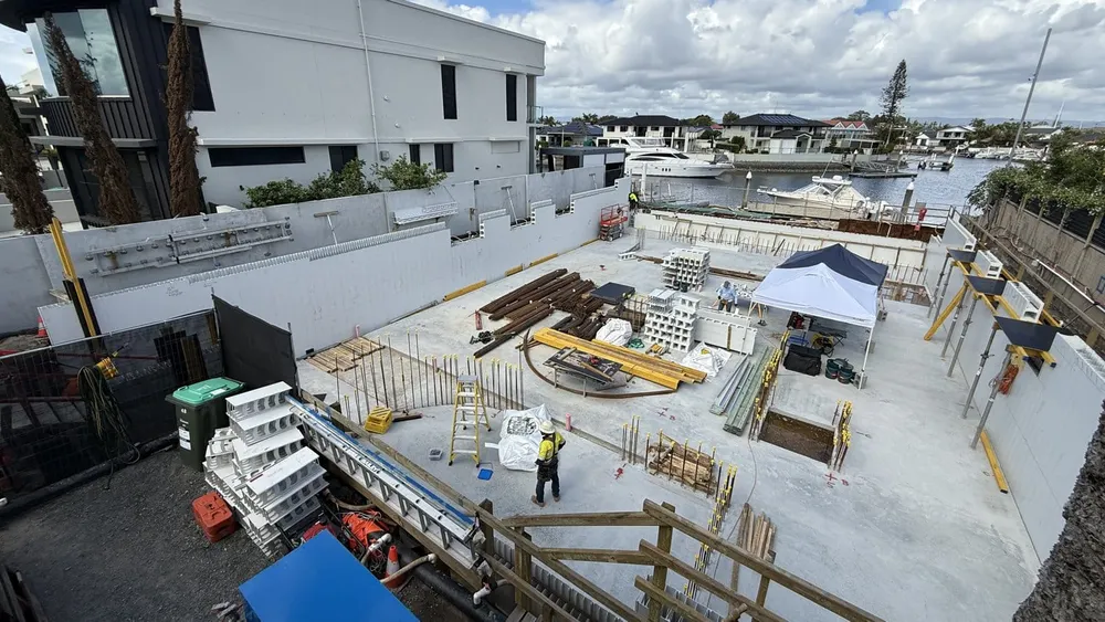
Last time (Post 55) we stood up the Rediwall basement walls. This is a short one: how the steel actually gets into those walls before the core fill goes in.
Cutting the walls to height
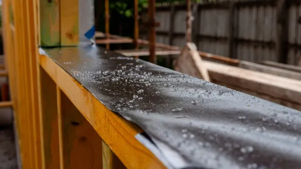
The walls are 3 m high. We bought stock-length panels, so today we cut them down to the underside of the ground floor slab. That's where the slab formwork will sit.
We cut the inside face only. The outside face is left a little higher, for two reasons:
- An edge board for the slab. The ground floor slab is poured up against it, so it gives a clean edge, and the walls above can connect to it.
- Less concrete where it shouldn't be. When the slab is poured, it stops concrete spilling down behind the wall, into the gap where the waterproofing and gravel go.
Dropping the verticals in
The way we do it is simple. One person loads the bars and hands them up to me in the scissor lift, and I run up and down the wall dropping them in from the top.
- N16 bars at 250 mm centres, on each face of the wall.
- They line up with the starter bars that come up out of the slab. Each vertical sits beside its starter and laps it, so the wall is tied to the slab.
- Horizontal bars run along each face. They were threaded through the panels as the walls went up.
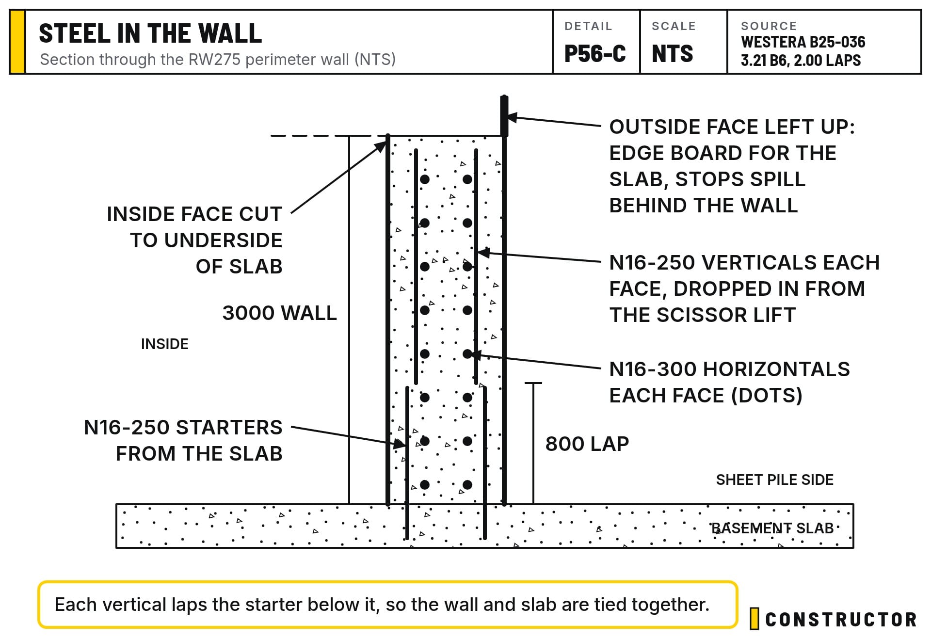
Westera's drawings use Dincel, and we're using Rediwall RW275 in its place. It's the same idea: a hollow PVC formwork you fill with concrete. Westera's steel details still apply. The wall steel is N16 verticals at 250 each face and N16 horizontals at 300 each face, with 50 mm cover, and N16 bars lap 800 mm.
The corners take the time
Corners are the slow part. Each one is propped and braced on the inside face, and the steel at a corner is more than straight bars.
Where two walls meet, straight horizontal bars can't turn the corner. So at every corner there are hooked bars, one for each horizontal bar, on the outside face and the inside face. They're bent to an L and lap the horizontals in both walls, so the two walls are tied together and act as one piece. You'll hear me call them L bars in the video. Westera's detail calls for N12 hooked bars, lapping 550 mm.
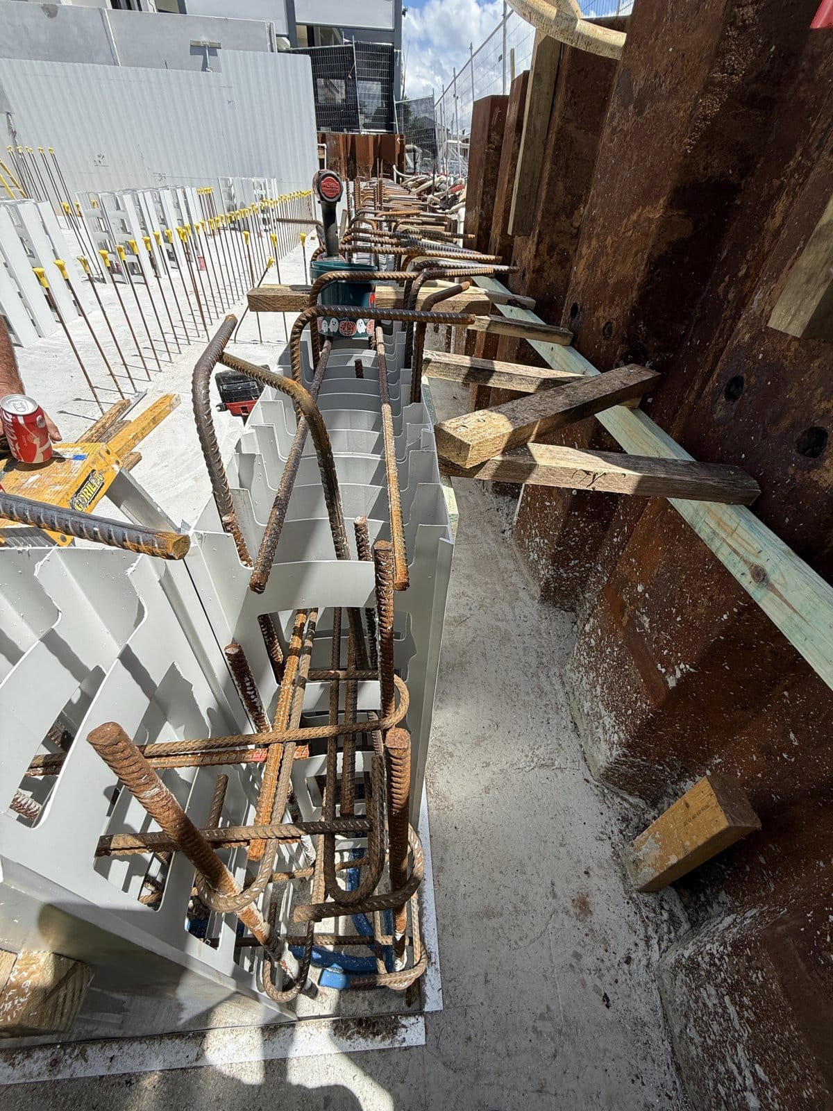
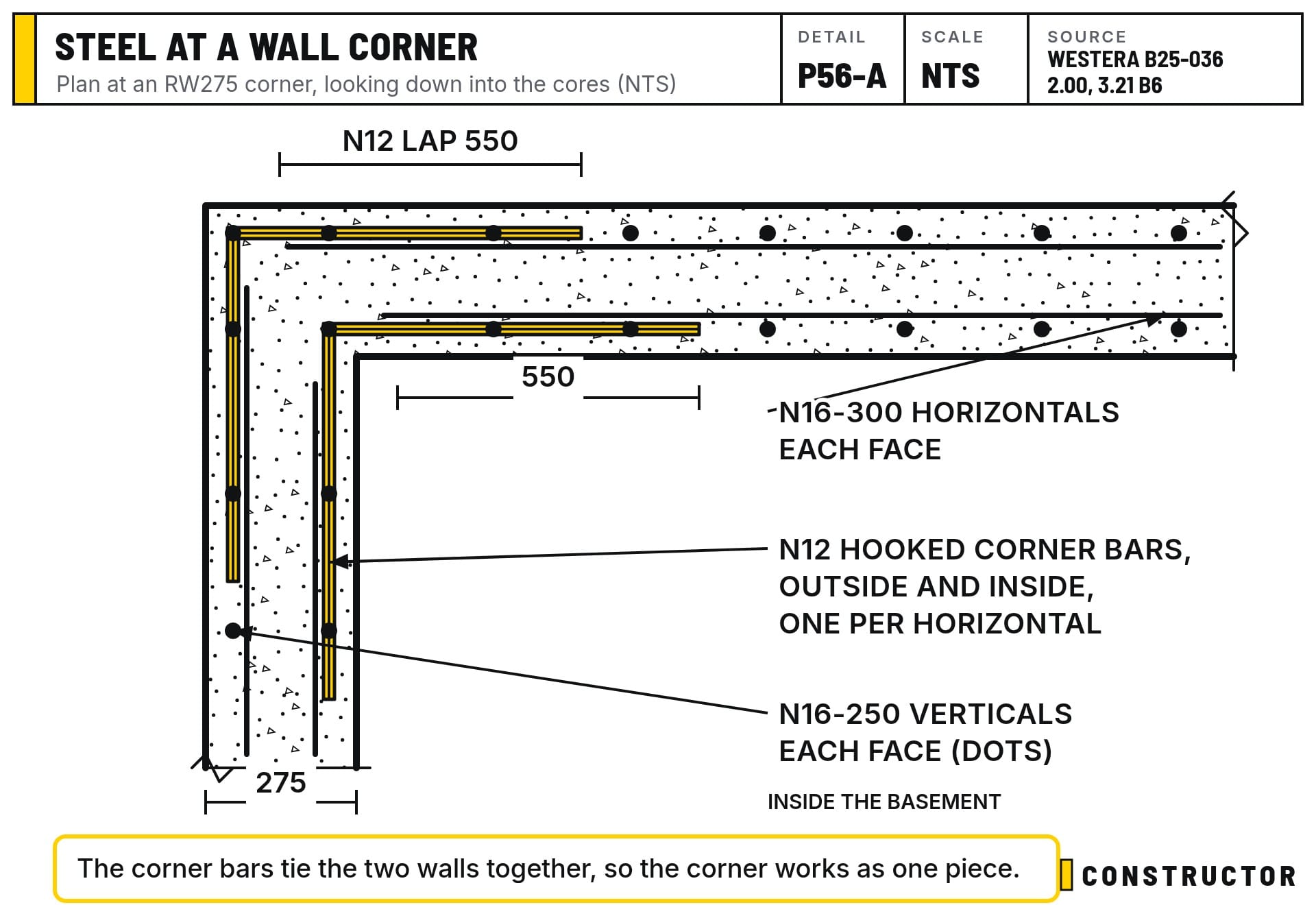
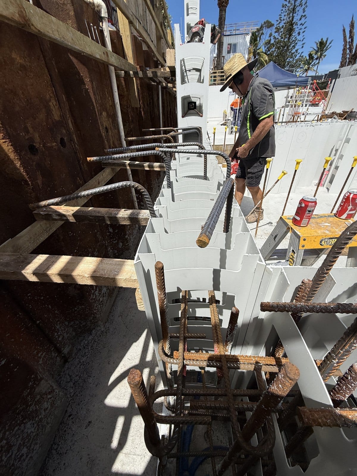
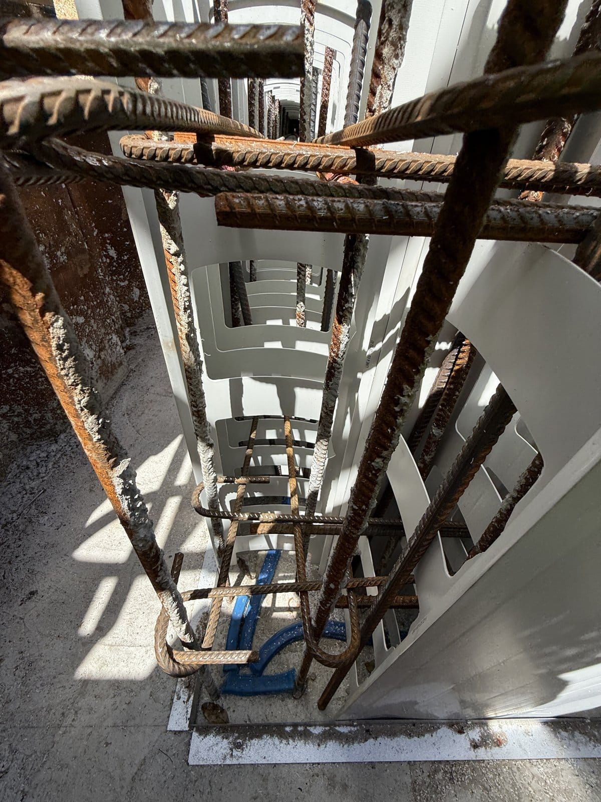
We'll come back tomorrow with more L bars. It's the easy part: they just go in.
Lintels over the windows
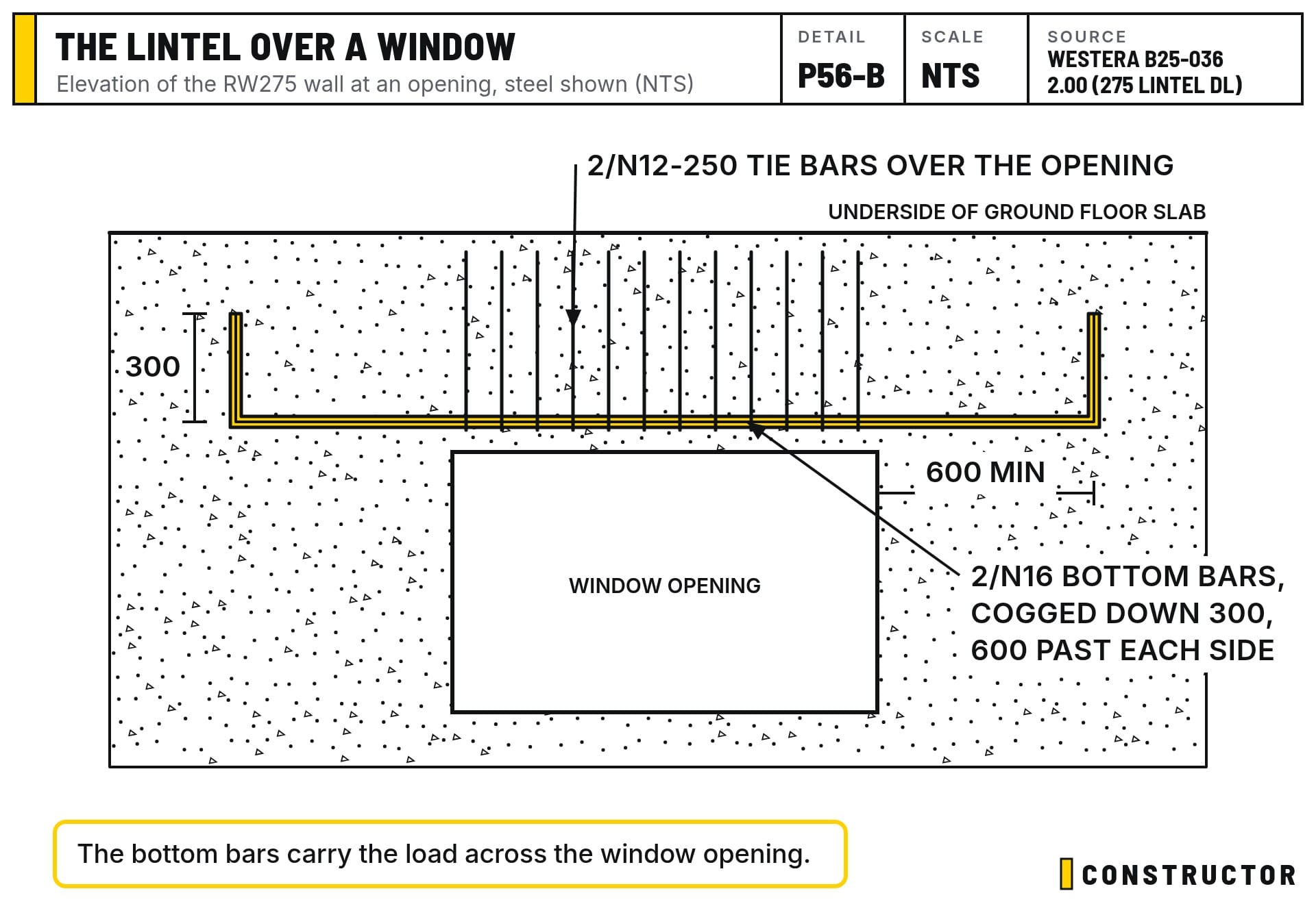
There are window openings in two of the basement walls, for ventilation. They'll take sliding sash windows, so the basement can be opened up to get fresh air through. The guys have started forming the openings. Above each window there's a concrete lintel: a beam formed in the wall, with a steel cage inside, so the concrete flows through and the wall above is carried across the opening. The formworkers weren't on site today, so they're back tomorrow to finish the cages and the formwork.
Conduits before the concrete
Anything electrical that runs inside these walls or columns has to go in before the pour. Once they're full of concrete, there's no getting a cable through them later.
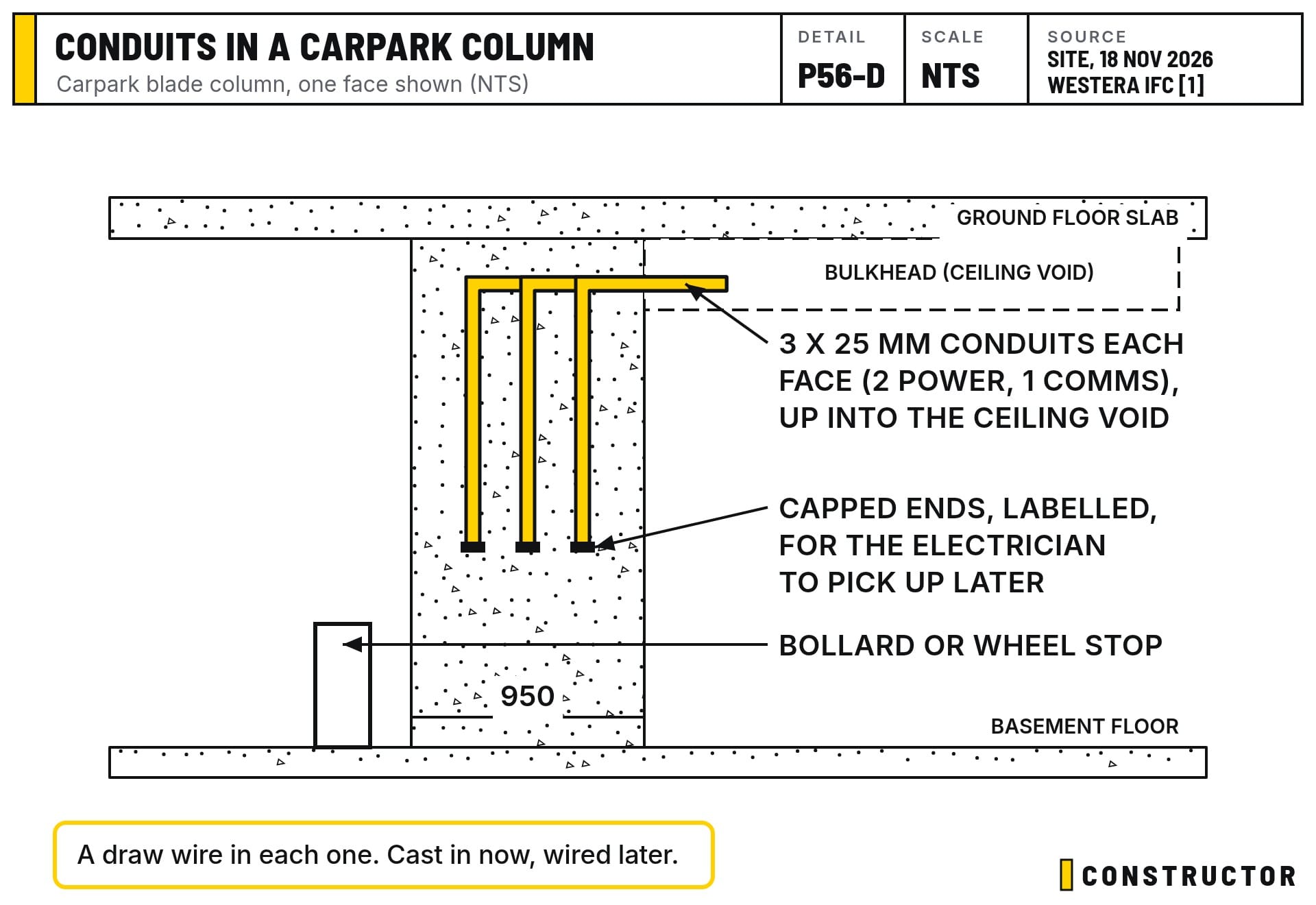
A conduit is just a plastic pipe cast into the concrete, so the electrician can pull cables through it later. Nothing is cast in yet. Today we're installing three 25 mm conduits on each face of the two carpark columns, for the electrical rough-in:
- Two for power and one for comms on each face, so a future EV charger can go on whichever side of the column suits the car.
- Up inside the column and out into the ceiling void, where the cables can run back to the switchboard.
- A draw wire in every conduit, with the ends capped and labelled, so they can be found and used later.
- Fixed to the steel so nothing floats or moves when the concrete goes in.
- Never in the waterproofed outside face of the RW275 walls. A hole there is a leak.
- Checked by the engineer. Conduits inside a structural column need the engineer's OK, so they don't clash with the steel or weaken the column.
The comms conduit is for the charger's data connection, which we covered in Post 55. A bollard or wheel stop in front will keep cars off the chargers.
Bracing before the pour
The columns are still to be formed, so for now we're bracing this wall back to a nib wall. We built the nib in RW275 instead of RW200, because we had a heap of RW275 offcuts. We ordered RW200 too, and that will be used later.
At the same time, back-propping is going on:
- Screw the wall to the track from behind, to lock the bottom in place.
- Brace with 90 x 35 timber. It's the green treated stuff, only because there's a lot of it around. These are 4.8 m lengths.
- Push-pull props at mid-span, arriving tomorrow.
Setting up for the pour
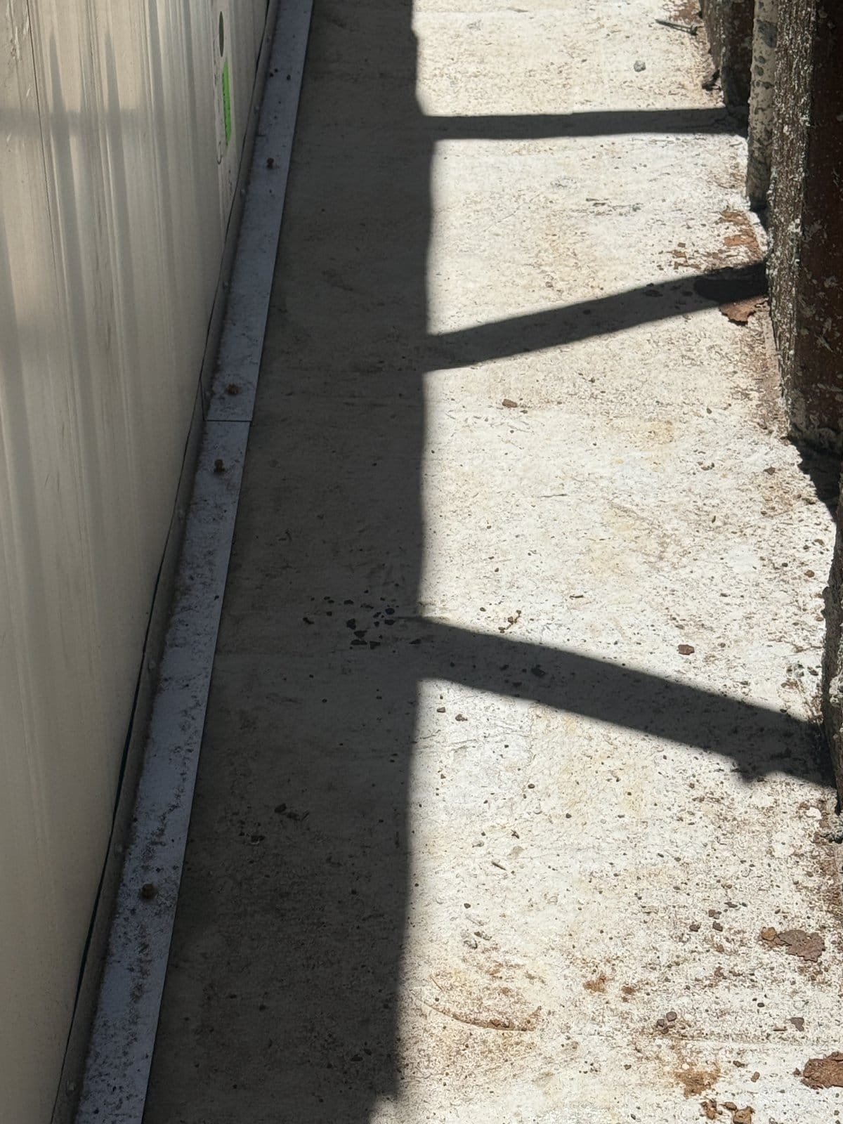
A tidy site is a safer site, so we clean up as we go. People are also less likely to throw rubbish around a site that's already clean.
Everything has its place: reinforcement, form ply, the L bars in one pile, LVLs for the formworkers, and FC sheet for the end caps that seal off the ends of the RW275 walls.
We're also adding a second power supply. At the moment the meter box is on the other side of the site, so leads run across the ground. Once the walls are formed we'll bolt timber to the wall and set up a sub-board there, then jump it up a level each time we go up. That keeps the leads off the floor.
There were six of us on site today and there should be around ten tomorrow. Two deliveries came in:
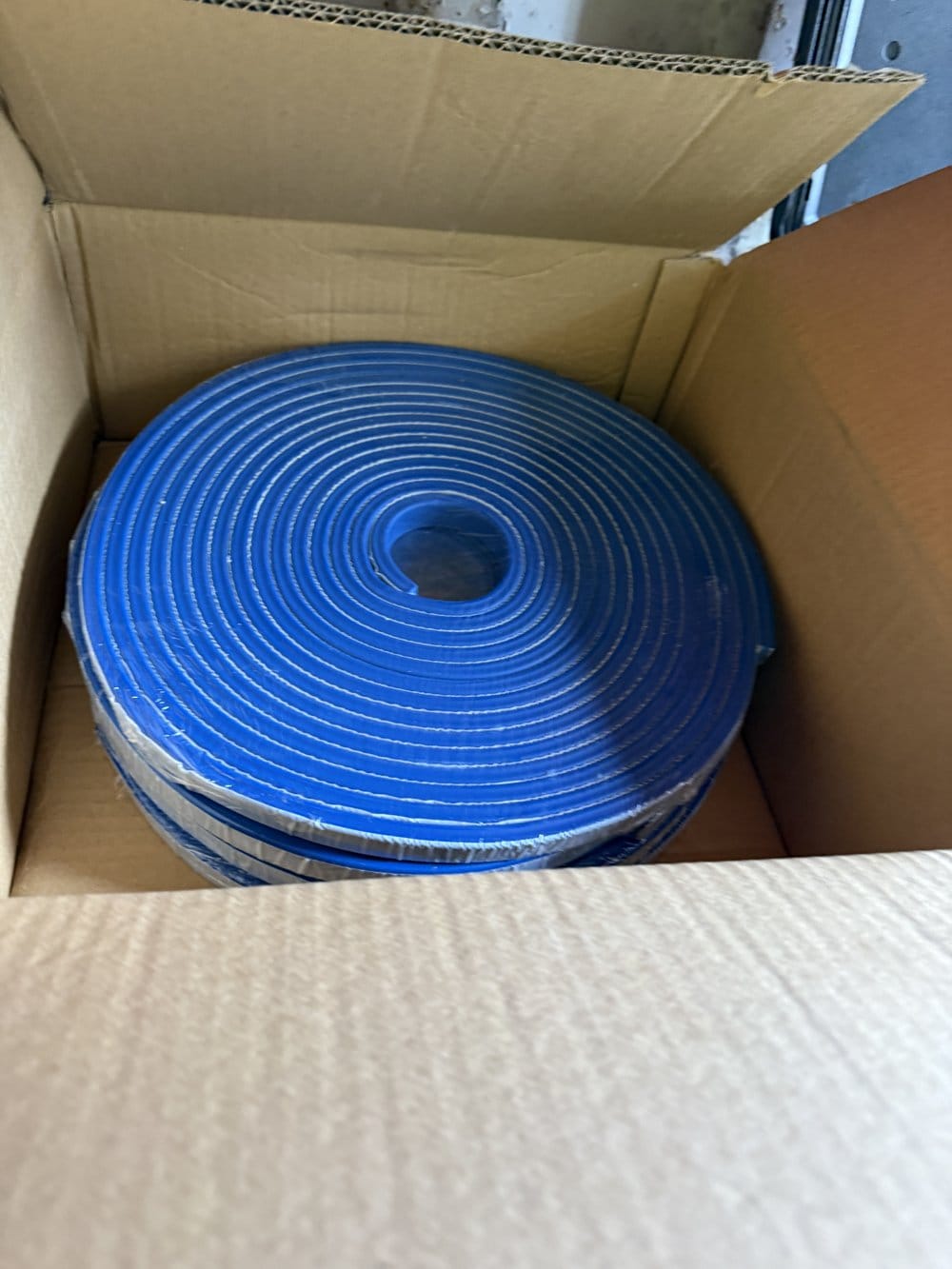
- The waterproofing products, with more stored in the container out of the sun. The crane will lift them down tomorrow.
- Another scissor lift, a 19 foot one.
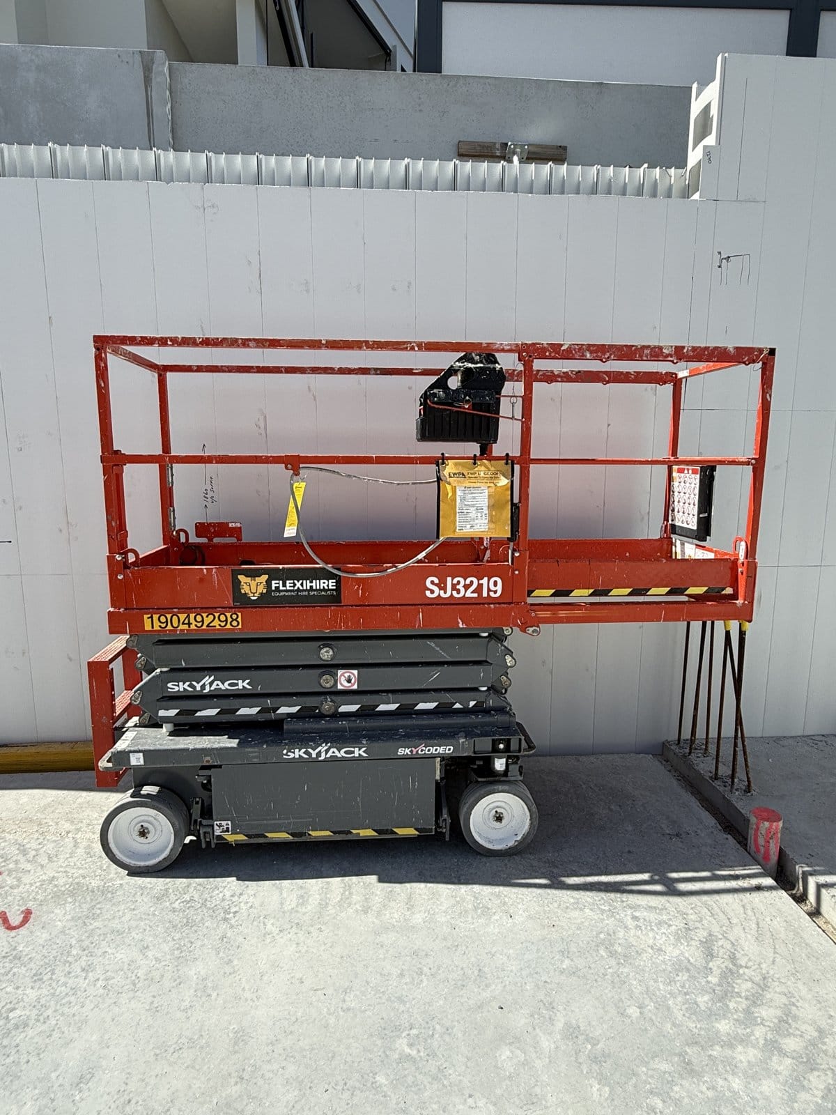
For the pour there will be one scissor lift with the crew placing the pumped concrete, a second with the crew vibrating it, and a mobile scaffold as well.
If you're building a house with block or formwork walls, the same rule applies: get the steel checked before the concrete goes in. Our C5 Pre-Pour Slab Inspection Checklist covers steel, cover and laps, and the same checks work for walls.

C5 - Pre Pour Slab Inspection Checklist
$119.00 AUD
Last updated 28 Oct 2026 · Revision 4 · Free updates for life
Checklist Type: Major (Base Stage)
Form Factor: Fillable, print-ready PDF (A4, 30 pages)
When to use: Base stage: after the slab is prepped, before concrete is poured
A 95-point pre-pour slab checklist. Check setbacks, boxing, membrane, pipes and steel after the slab is prepped and before concrete is poured, while fixes are still simple.
✓ Authorship verified on the blockchain · View certificate